Riptide Realtime Design, development and consulting for computer and digital hardware/software solutions, working with embedded systems, FPGAs, SoC FPGAs, and PC board-level technologies.

For over 20 years Riptide Realtime has been designing and building electronic signal processing software, hardware and systems for adaptive optics.
We provide complete reconstructor signal processing systems and fast Xinetics deformable mirror interfaces. Our high frame rate systems use FPGA-connected camera and DM interfaces, and an FPGA-based wavefront reconstructor. We have also delivered lower frame rate systems running a real time Linux variant on PC hardware. In both FPGA- and RT Linux-based systems the signal processing component has a guaranteed maximum latency.
Our AO signal processing systems use our Adoptics Software, whose development was driven by the needs of optical engineers and scientists implementing experimental and prototype systems. The software features a GUI with real time feedback and control during closed-loop operation, and provides many interactive tools for testing and aligning the system and its electro-optical components.
Typically a deliverable signal processing system will be configured for a customer-specified camera, DM and optionally a tip/tilt (FSM) mirror. The customer specifies the wavefront sensor geometry and its mapping to the DM actuators by means of control matrix coefficients. Processing time and frame rate depend on these specifications. (Details)
Our FPGA-based systems use our existing IP cores for a typical signal-processing chain (e.g. Hartmann wavefront sensor, control matrix multiply, control-law application). However we have delivered several systems with variations of the above, including our FPGA implementations of customer-specified algorithms.
Most customer systems for which we have supplied hardware and software components have used Xinetics DMs of various sizes, and cameras supporting the Camera Link standard. We have also delivered systems supporting custom camera interfaces, MEMs mirrors and Optical Physics DMs.
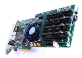
The MHVA4 Fast PCIe Interface to Xinetics HVA will write signed 16-bit actuator data to up to four SOR-422 differential data channels at 20 MHz per channel*. Interface timing meets Xinetics Gen 3 requirements. The board requires a 8x or greater PCIe slot and the software driver requires a 2.6 or later Linux kernel. The board optionally comes with four 3-meter twisted pair ribbon cables to connect to Xinetics HVA electronics. Source code for the driver and for a demo application is included.
*Actual performance across the PCIe channel is dependent on the motherboard's PCIe implementation, and competition with other motherboard devices.
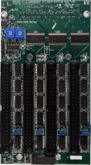
The MHVA4F Fast FPGA Interface to Xinetics HVA can write signed 12-bit actuator
data (sign-extended to 16 bits by the interface) from an FPGA carrier board simultaneously to up to four SOR-422 differential data
channels at a common clock rate determined by the user. The default is 20 MHz per channel
as per the SOR-422 specification. When data is streamed to all 4 channels simultaneously from the FPGA this corresponds to an 80 mega-actuator per second bandwidth
to the mirror.
Interface timing meets Xinetics Gen 3 requirements.
A 2-channel DAC option allows the board to output analog voltages for control of tip/tilt steering mirror systems. This overcomes the need for another FPGA carrier
board slot just to handle tip/tilt output.
The MHVA4F is a mezzanine board
which supports the VITA 57.1 FPGA Mezzanine Card (FMC) connection specification by using a
subset implementation of the low pin count (LPC) connector. Due to the size of
the connectors needed for the Xinetics HVA interface's ribbon cables the board does not
meet VITA 57.1 dimensional specifications for length and height.
The board has been tested
plugged into the FMC LPC connector (J5) of a Xilinx Zynq ZC706 evaluation board. The MHVA4F board
optionally comes with four 3-meter twisted pair ribbon cables to connect to Xinetics HVA electronics.
A VHDL driver core and test bench is included.
Real Time Processor System
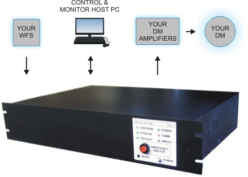
RTP Unit and Peripheral Connections
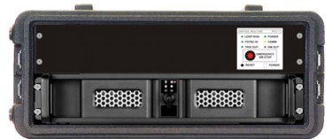
RTP and Host PC in Rack Case
The Real Time Processor System consists of the RTP rack-mount processor, a host PC, and the Adoptics software.
The Riptide RTP is a 2U rack-mount processor which implements an AO wavefront reconstructor in an FPGA. It runs the processor side of the Adoptics software. The RTP may be run in an optional turn-key stand-alone mode or in conjunction with a TCP/IP ethernet-connected host PC running the Adoptics client side GUI software. The RTP incorporates a Base/Medium/Full Camera Link interface and a 4-channel Xinetics DM interface. Both interfaces are connected directly to the FPGA, assuring high throughput at the maximum possible rates specified by the Camera Link and Xinetics protocols. An SFP/SFP+ module connector is also connected to the FGPA and is available for a Xilinx Aurora serial interface implementation. Other interfaces are available.
Processing time and frame rate depend on several customer-specified factors. (Details)
Front panel LEDs monitor various reconstructor functions and I/O activity. A pushbutton allows manual shut-off of DM output. A rear-panel BNC connector provides a user-controllable 5V TTL-level trigger. There is an opening in the rear panel for Camera Link, Optical Fiber and DM interface cables, which connect internally to their respective interfaces.
Weight (kg/lb): 3.8 / 8.4, Dimensions exclusive of rack mount front panel (mm/in): 443 x 300 x 83 / 17.44 x 11.81 x 3.26 (Approx.), Voltage: 115VAC Power consumption: 75W (Approx.)
The host PC is a rack-mount unit with a PCIe bus. The bus is available for non-real time boards that may be relevant to the AO system, such as motion control interfaces. The PC host uses from 2U to 4U of rack space depending on how many (if any) PCIe bus boards are installed. The host PC runs a version of Linux and the host side of the Adoptics software.
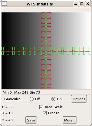
Example of an Adoptics Intensity Display with a bi-cell WFS alignment graticule

Example of an early version of an Adoptics DM Diagnostic Display
Standard Features
- FPGA Reconstructor
- Deterministic real time operation
- Very low latency (high frame rate)
- Shack-Hartmann wave front sensor algorithm
- Hudgin wave front sensor geometry
- Reconstruction matrix multiply with customer-supplied coefficients
- Piston removal
- Leaky integrator control law
- DM Actuator slaving
- DM Emergency Stop
- Real Time Interactive (Details)
- Camera Link camera support (Base, Medium, Full)
- User-controllable trigger output for camera, etc.
- Xinetics DM Support
- Customer-defined mirror map (Master, slave and static actuator designation)
- Optical alignment tools for camera, DM and system optics
- Interaction matrix measurement with actuator hysteresis compensation
- Extensive diagnostic tools for camera, reconstructor system and DM
- Dynamic DM stress reduction (Details)
- Comprehensive documentation
Optional Features
- Data logging - Time-stamped lossless real time recording of reconstructor chain data, including WFS input and DM output (Details)
- On-the-fly control matrix coefficient replacement
- Turn-key stand-alone operation of the RTP unit (w/o host PC)
- Custom implementation of Xilinx Aurora fiber protocol communication
- Custom implementation of customer-supplied algorithms
- Custom integration of host PCIe board drivers
Riptide Realtime has worked closely with customers choosing to have their own reconstructor algorithms implemented in either real time Linux or FPGA processing systems. We develop FPGA/SoC designs on both Xilinx and Altera platforms.
We have over 20 years of experience in interfacing 3rd party AO system components, such as cameras and DMs. This includes building and integrating physical interfaces, writing Linux drivers, and designing FPGA logic for interfaces to FPGA, PCIe and PCI-X hardware for the following devices:- Cameras by Basler, FLIR, Xenics, Photon Focus, Point Grey and Astronomical Research Cameras
- DM amplifiers and DMs from Xinetics and Optical Physics
- Signal processing electronics
- Various hardware such as A/D-D/A converters, telescope positioning encoders/controllers, and motion controllers
- Embedded systems
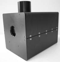


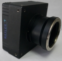
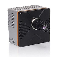
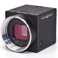
Riptide Realtime also consults, and designs and builds instrumentation, control systems and custom prototypes. We have delivered a diverse array of products, including hyperspectral imaging, DSP-based radar signal processing and an electric vehicle infrastructure monitoring system.

100" Hooker Telescope at Mt. Wilson


Technical support: support@riptiderealtime.com or 310-490-3233

Reference Documents:
FMC (LPC) Connection TableThe FPGA reconstructor has "zero-frame" latency, meaning that each frame's camera readout is processed and output to the DM before the next frame's exposure is triggered. Reconstructor processing time is dependent on the following variables:
- Number of wave front sensor subapertures and DM actuators
- Subaperture geometry
- Camera integration time
- Camera readout timing
- DM data output time
- Desired DM actuator settling time
- FPGA latency (logic processing time)
Conceptually, the processing chain tasks are camera readout, process, DM output. However, in our highly parallelized and pipelined FPGA logic tasks interact in complex ways, which makes a determination of FPGA latency (processing time) based on the above variables non-trivial. Following is a real-world example of the processing chain in an existing system, the timing of which may be useful. The characteristics of the system are:
- Base Camera Link input, 80MHz pixel clock
- Readout of 32x32 12-bit pixels, 10x10 region of interest, bi-cell subapertures
- Processing chain: X/Y Gradient calculation, control matrix multiply, piston removal, control law application
- 10x10 actuator DM output in 5us
Assuming a 1us integration time, the time from start of exposure to completion of DM output is under 20us. The resultant maximum frame rate is 50KHz. If adding 8us physical actuator settling time to this, the resulting frame rate is about 35KHz.


Selected publications:
"Stokes parameter imaging of scattering surfaces", JD Barter, PH Lee, HR Thompson, TG Schneider, SPIE, July, 1997"Real-time distributed processing in the Mt. Wilson 100 inch Hooker telescope adaptive optics system", T. Schneider, J.C. Shelton, SPIE, March, 2000
"High-speed DSP assembly language code for processing wavefront sensor pixels", T. Schneider, J.C. Shelton, SPIE, March, 2000